Table of Contents
Table of Contents
Introduction
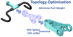
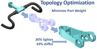
Topology Optimization is a powerful finite element analysis (FEA) tool used in engineering and product design to find the optimal structural shape within a given design space. This tool allows engineers to design the lightest part that will achieve the desired design objects or create a part with a maximum strength-to-weight ratio. In this article, I’ll answer two questions: What is FEA Topology Optimization, and how to use it in SolidWorks Simulation? I’ll explain how the various settings in the SolidWorks Topology Optimization tool affect the results as well as discuss how topology optimization differs from the SolidWorks parametric optimization tools.
Think about how weight is a factor in so many of our designs. We often need to reduce the weight of our designs to reduce material costs and shipping costs. Or, we need the performance benefits of a lighter yet stiffer design. Topology optimization is the tool that allows us to achieve the ultimate part design with the least amount of material.
What is FEA Topology Optimization
Topology optimization is a design optimization technique used in engineering and product design to find the optimal material distribution within a given design space. The goal is to determine the best configuration of materials and their distribution to achieve specific performance objectives while minimizing the use of resources such as material or weight.
Here’s how topology optimization works:
- Design Space: You start with a predefined design space, which represents the largest volume or area in which your part will be created. This space is divided into a grid of finite elements. (Click here to learn more about Finite Element Analysis.)
- Objective and Constraints: You define the objectives you want to achieve, such as maximizing stiffness, minimizing weight, or increasing the part’s fundamental frequency. You also set constraints, which can include factors like material properties, manufacturing limitations, or stress limits.
- Finite Element Analysis (FEA): FEA is used to simulate how the structure or component behaves under the defined loads and boundary conditions. This analysis provides information on stress, strain, and deformation within the design.
- Iterative Process: The optimization algorithm iteratively removes material within the design space to reduce weight while meeting the specified constraints. The software organically removes elements based on where and how the loads are transferred through the part. Elements that don’t contribute to the overall stiffness of the part get removed.
- Convergence: The optimization process continues until a convergence criterion is met, indicating that the design has reached an optimal configuration or a satisfying solution.
Topology optimization is particularly valuable when designing complex parts, as it can uncover unconventional and highly efficient designs that might not be apparent through traditional design methods. It can help reduce material usage, improve structural integrity, and enhance overall product performance, making it a powerful tool in modern engineering and product development.
SolidWorks introduced Topology Optimization in their 2018 release. It is available with the SolidWorks Simulation Professional and Premium versions of the software.
How Topology Optimization Differs from Parametric Optimization
As the name suggests, parametric optimization is an FEA process that optimizes a design by changing various design parameters (e.g., dimensions) until the desired design goal is achieved. The parametric optimization is called a “Design Study” in SolidWorks.
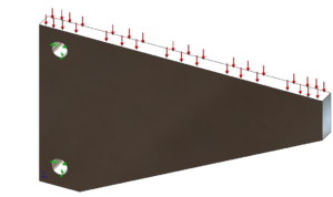
So in the parametric optimization of this bracket, for example, we specify constraints, like maximum stress or displacement, or minimum factor of safety. And, then specify a goal such as minimizing the weight. We then pick the dimensions that we want to modify and we give a range of values for each dimension.
The parametric optimization process then automatically varies all the dimensions, looks at the results of each of the scenarios, and then selects the optimized scenario, the one with the lowest part weight in this case.
Design optimizations are indeed valuable for streamlining the optimization process, especially when we have a clear understanding of which design dimensions should be modified. However, their effectiveness relies on a predefined design and parameters, meaning we need some prior insight into the desired final design. Additionally, the optimization output remains constrained by the defined parameters, potentially limiting the extent to which the design can be truly optimized.
On the contrary, topology optimization does not require the designer to have foresight into what the final design will look like. The designer only needs to specify the maximum design space available, the design objectives, and the design constraints. We don’t have to have features or dimensions defined for the shape to be adjusted, meaning you don’t have to know what the final design should look like before you start the study. This makes a Topology study a powerful tool for fully optimizing the stiffness-to-weight ratios of parts.
We can start with a simple model of our maximum design space and all the mating features and loads, then let the topology study show us what the optimal design would look like.
How to Use Topology Optimization in SolidWorks
The following section assumes you have experience setting up a standard FEA study in SolidWorks Simulation.
- Create a model of the part that fills the entire design space available for that part. Include any mating faces that will mate to surrounding parts in the assembly. (In later steps we will choose to preserve these faces from being altered during the optimization process.)
- Create a static FEA study of the part, defining the material, loads, and fixtures as normal. Run the study validate the study setup and ensure stresses and displacements are allowable. (If they are not, running an optimization to remove material isn’t going to fix this.)
- Create a Topology Study. You’ll need SolidWorks Simulation Professional or Premium to see this option.
- Copy the Parts, Fixtures, and External Loads folders from the static study to the topology study.
- Choose your design goal by right-clicking on “Goals and Constraints” in the study tree and selecting the desired goal. (You can only choose one goal per study. The three goals available are :
- Best Stiffness-to-Weight Ratio – This goal maximizes the stiffness of the part while reducing its mass by a specified amount.
- Minimize the Maximum Displacement – This goal works by selecting a vertex on the part where the displacement is to be minimized. A constraint is then added to reduce the mass of the part.
- Minimize Mass – This goal reduces the mass of the part as much as possible while maintaining the displacement constraint set by the user.
- Select the desired constraints for the design goal selected above. After selecting your desired goal a “Goals and Constraints” dialog window will open allowing you to select your desired constraints. Your available constraint options are:
- Mass Constraint – Specifies a target mass by which the part will be reduced as either a percentage of the initial part mass or as an absolute value.
- Displacement Constraint – Specifies the maximum displacement as a specified value or as a factor to multiply by the maximum displacement calculated in the static study. The displacement can be measured from either a user-specified vertex or as the maximum displacement observed across the entire part.
- Frequency Constraint – (Available in SolidWorks 2019 and later.) For each mode shape desired, specifies a minimum allowable frequency, a maximum allowable frequency, or a permissible frequency range.
- Stress/Factor of Safety Constraint – (Available in SolidWorks 2019 and later.) Specifies a maximim permissible von Mises stress or a minimum factor of safety. Note: I have found that adding a Stress or Factor of Safety constraint adds considerably to the analysis solve time.
- Apply Manufacturing Controls if desired by right-clicking on “Manufacturing Conrols” in the study tree and selecting one of more of the following options:
- Preserved Region – Select faces in your model that will not be modified during a topology optimization. You can freeze regions of your model that are contacting other parts, such as regions that are used to support the model and regions that form bearing surfaces. These regions do not participate in the topology optimization and remain unchanged. You can also specify the depth of the region to be preserved. Note: In the study properties you can also choose to automatically preserve regions that have fixtures or loads.
- Thickness Control – Apply minimum and/or maximum member size restrictions for a topology optimization that prohibits the creation of very thin or very thick regions that may be difficult to manufacture.
- De-Mold Control – Prevents the formation of undercuts and cavities and ensures that the optimized shape can be extracted from a mold. Select pull direction (i.e., the direction the part would be pulled from a mold), midplane (as if the parting line of the mold is along the midplane of the part), or stamping direction (if the optimization removes an element from the part, it also removes all the elements behind or in front of the element) The image below shows how each of these options affects the optimization of the simple bracket.
- Symmetry Control – Causes the results to be symmetric about specified planes. You can control half, quarter, or one-eighth symmetry.

FEA Topology Optimization De-mold Control Options
- Mesh the part. Unless a Stress/Factor of Safety constraint was specified, use draft quality elements that are suitable for determining stiffness, but not stress, to speed up the solving time. SolidWorks also recommends using the standard mesher rather than the curvature-based mesher. Mesh element size will affect the results as shown in the example below.
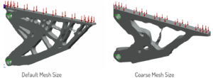
FEA Topology Optimization Mesh Effects - Run the study.
- Modify Results. Right-click on the resulting Material Mass plot to edit its definition. Drag the material mass slider to add or remove material. Drag the smoothing slider to coarsen or smooth the par as desired.
- Export the optimized part. Right-click on the Material Mass plot and select “Export Smoothed Mesh”. The material mass plot can be exported as a graphics, solid, or surface body.
The exported body can be used as the foundation for creating the final model. It’s a good idea to rerun the FEA on the final part rather than relying on the stress and displacement from the topology optimization.
What is Topology Optimization – Conclusion
FEA topology optimization is a powerful tool that can greatly enhance the design process allowing for optimized designs that may not be apparent through traditional design methods. By harnessing the power of FEA topology optimization, engineers and designers can create lightweight and efficient designs that meet performance requirements while minimizing material usage.
If you want to learn more about the benefits of Topology optimization or need assistance optimizing one of your designs, don’t hesitate to reach out to one of the Finite Element Analysis experts at Situs Engineering.
